Wiring Diagrams
3 pin XLR wiring diagram
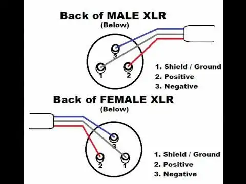
- Pin 1 → Shield/Ground
- Pin 2 → Positive
- Pin 3 → Negative
3.5mm to XLR female
- Pin 1 → Ground/Sleeve
- Pin 2 → Ring
- Pin 3 → Tip
3.5mm to Duel XLR male
Left
- Pin 1 →Sleeve
- Pin 2 →Tip
- Pin 3 → Sleeve
Right
- Pin 1 → Sleeve
- Pin 2 → Ring
- Pin 3 → Sleeve
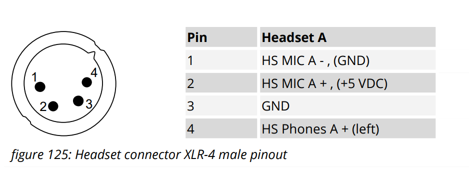
4 Pin Comms wiring
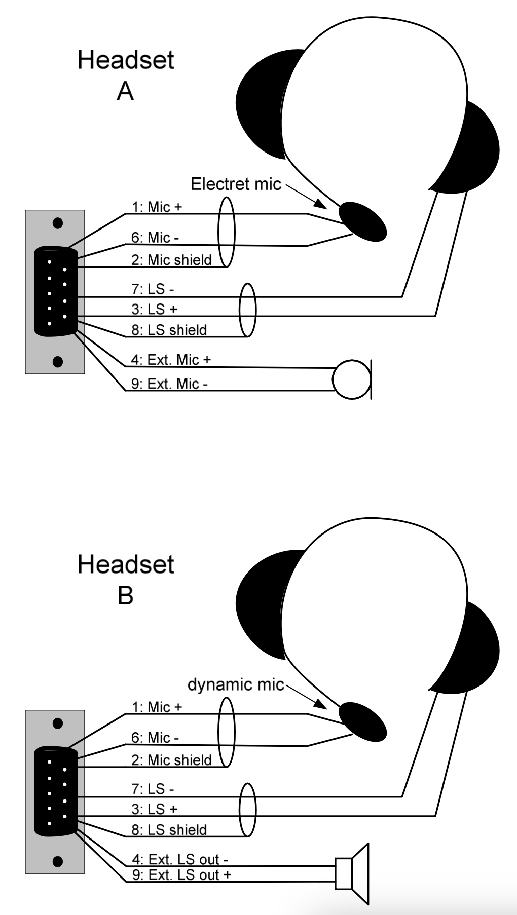
Headset wiring
| Brand | pin1 - mic low | pin2 - mic high | pin3 - ear low | pin4 - ear high (L or L/R) |
|---|---|---|---|---|
| Beyer | shield | blue | black/white | red/org |
| D2N Phone hand-held | Red | Black | green | yellow |
| Reidel Pro | yellow/shield | green | blue & brown |
red/org ear L/R high |
| Riedel Air | shield | red | blue | white |
| Riedel Max | white/shield | brown | green/blue | yellow/red |
| Senn hd25 | red/shield | blue | green/grey | white/yellow |
| HMD46 | blue & shield | red | orange & white | brown & green |
| Telex PH-44R5 | blue & shield | white | black | red |
| Telex twin | blue &shield | white | yellow & black | red |
| Riedel Run | Shield | green | pink | red |
| Clearcomm CC-300 & CC-400 | Shield & Green | Yellow | Red & Orange | Blue/Brown |
| Hytera RSM | Green & Shield | Green | Blue & Brown |
Standard Pin definition
Pin 1 = Mic Negative
Pin 2 = Mic Positive, (+5v Electrate)
Pin 3 = Speaker Negative/ground
Pin 4 = Speaker Positive
Panel Wiring
RSP-1231HL
5 Pin Comms Wiring
| Pin 1 |
Pin 2 |
Pin 3 |
Pin 4 |
Pin 5 |
|
| Max | white/Shield | brown | green & blue | red | yellow |
| Riedel Pro | Yellow |
Green |
Shield & Blue & Brown |
Orange |
Red |
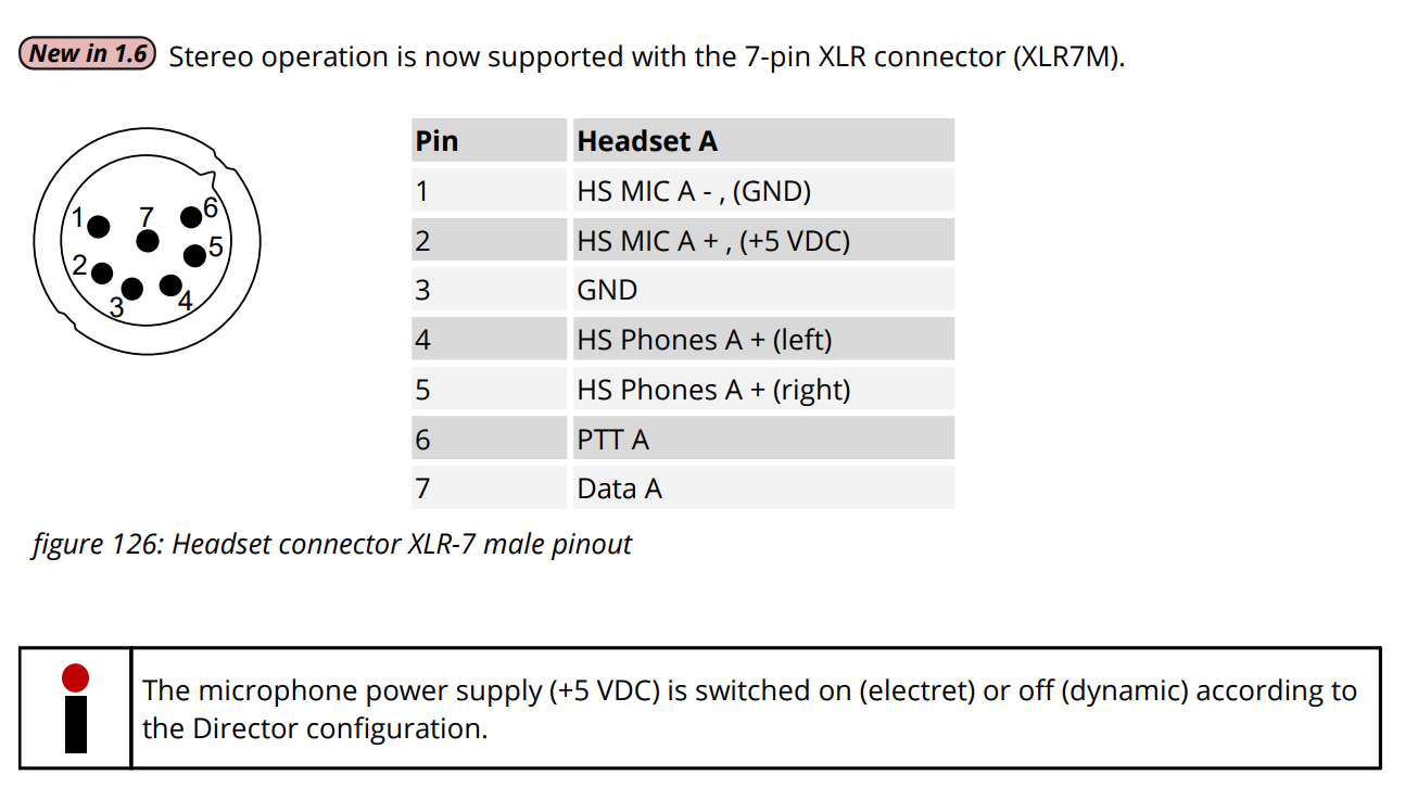
7 Pin Comms Wiring
Headset & RSMs
| Pin 1 |
Pin 2 |
Pin 3 |
Pin 4 |
Pin 5 |
Pin 6 |
Pin 7 |
|
| Hytera RSM | Green |
White |
Grey & Red |
Yellow |
Yellow |
Brown |
N/C |
| Riedel Pro | Yellow |
Green |
Shield & Blue & Brown |
Orange |
Red |
N/C |
N/C |
| Max | white/Shield | brown | green blue | red | yellow | ||
N/C = Not Connected
RSP-1232
7 Pin Male to 4 Pin Female
| XLR7M | XLR4F | Wire Colour |
|
Pin 1 |
Pin 1 | Red |
| Pin 2 | Pin 2 | Green |
| Pin 3 | Pin 3 | Black |
| Pin 4 | Pin 4 | White |
| Pin 5 | Pin 4 | N/A |
| Pin 6 | N/C | N/A |
| Pin 7 | N/C | N/A |
N/C = Not Connected
RJ45 Comms Wiring
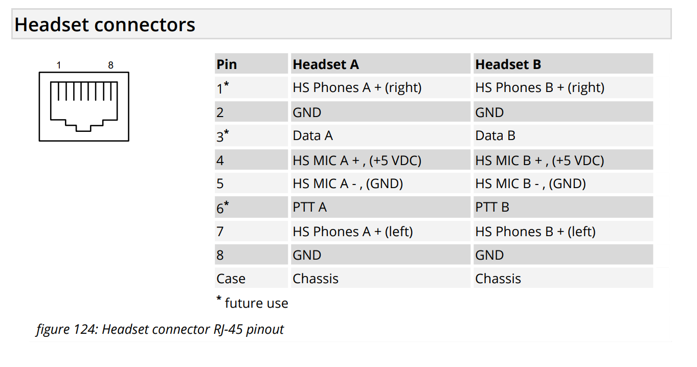
Headset Connector
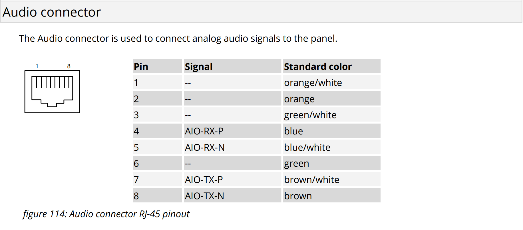
RJ45 AIO
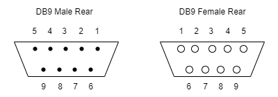
DB-9 DSub
1100 Series Panel - Headset connector
| Pin |
Headset A |
Headset B |
|
1 |
HS Mic +, +5v |
HS Mic +, +5v |
| 2 |
Chassis |
Chassis |
| 3 |
HS phones + | HS phones + |
| 4 |
Ext. MIC +, +5V | Ext. Speaker Out - |
| 5 |
Chassis (Ext. MIC shield) | -- |
| 6 |
HS MIC - | HS MIC -, +5V |
| 7 |
HS phones GND | HS phones GND |
| 8 |
Chassis (HS phones shield) | Chassis (HS phones shield) |
| 9 |
Ext. MIC -, +5V | Ext. Speaker Out + |
| Case |
Chassis | Chassis |
Notes: The MIC input at HS A is unbalanced. For unbalanced HS A MIC connect MIC + to pin 1 and MIC shield to pin 6. Pin 2 can be used for cable shield.
For unbalanced HS B MIC connect MIC+ to pin 1 and MIC shield to pin 6 and pin 2. Only dynamic microphones can be used symmetrical at this connector.
For unbalanced Ext. MIC connect MIC+ to pin 4 and MIC – to pin 9 and 2. Pin 5 can be used for cable shield. Ext. Out (LS): 2W, 4Ohm
1100 Series Panel - Audio In Out
| Audio In |
Audio Out |
|
| Pin 1 |
Audio In A + | Audio Out A + |
| Pin 2 |
Audio A shield | Audio A shield |
| Pin 3 |
Audio In B - | Audio Out B - |
| Pin 4 |
Ext. MIC + * | Ext. Speaker Out + * |
| Pin 5 |
Ext. MIC shield * | Ext. Speaker shield * |
| Pin 6 |
Audio In A - | Audio Out A - |
| Pin 7 |
Audio In B + | Audio Out B + |
| Pin 8 |
Audio B shield | Audio B shield |
| Pin 9 |
Ext. MIC - * | Ext. Speaker Out - * |
| Case |
Chassis | Chassis |
Note: * only in DCP version!
1100 Series Panel - GPIO
| GPIO In | GPIO Out |
|
| Pin 1 |
GPI 1 In + | GPO 1 Out A |
| Pin 2 |
GPI 2 In + | GPO 2 Out A |
| Pin 3 |
GPI 3 In + | GPO 3 Out A |
| Pin 4 |
+5V, max. 50mA | +5V, max. 50mA |
| Pin 5 |
GND | GND |
| Pin 6 |
GPI 1 In - | GPO 1 Out B |
| Pin 7 |
GPI 2 In - | GPO 2 Out B |
| Pin 8 |
GPI 3 In - | GPO 3 Out B |
| Pin 9 |
GND | GND |
| Case |
GND | GND |
DMX 5 pin
- Pin 1 - Ground/Common
- Pin 2 - Negative Data
- Pin 3 - Positive Data
- Pin 4 - Aux Negative Data
- Pin 5 - Aux Positive Data
DMX RJ45
- Pin 1 (white/orange) - Positive Data
- Pin 2 (Orange) - Negative Data
- Pin 3 (White/Green) - Negative Aux Data
- Pin 4 (Blue) - Unused
- Pin 5 (White/Blue) - Unused
- Pin 6 (Green) - Aux Negative Data
- Pin 7 (White/Brown) - Ground/Common
- Pin 8 (Brown) Aux Ground/Common
Comms Headset Tester
- pin1 → pin1&3 male xlr
- pin2 → pin 3 male xlr
- pin3 → pin1&3 female xlr
- pin4 → pin2 female xlr
RJ45 - Type A
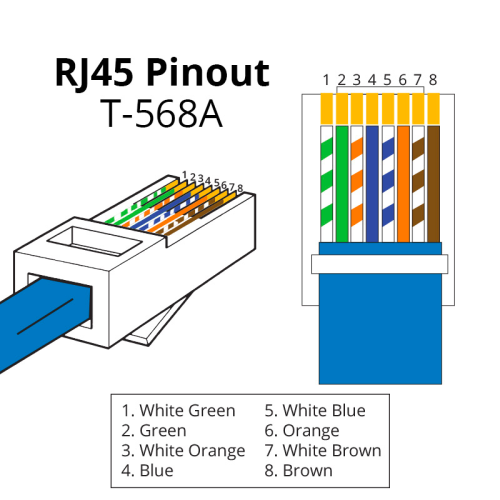
- Pin 1 - White Green
- Pin 2 - Green
- Pin 3 - White Orange
- Pin 4 - Blue
- Pin 5 - White Blue
- Pin 6 - Orange
- Pin 7 - White Brown
- Pin 8 - Brown
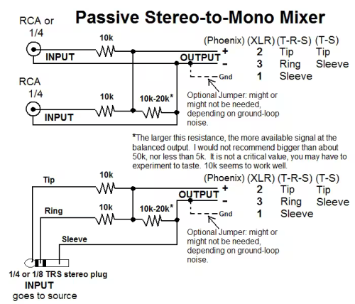
Stereo to mono - passive