# Wiring Diagrams ## 3 pin XLR wiring diagram
[![xlr-cable-design-new.webp](https://wiki.apointless.space/uploads/images/gallery/2023-09/scaled-1680-/xlr-cable-design-new.webp)](https://wiki.apointless.space/uploads/images/gallery/2023-09/xlr-cable-design-new.webp)
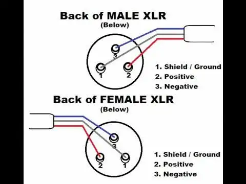
- Pin 1 → Shield/Ground - Pin 2 → Positive - Pin 3 → Negative
## 3.5mm to XLR female
- Pin 1 → Ground/Sleeve - Pin 2 → Ring - Pin 3 → Tip
## 3.5mm to Duel XLR male
**Left**
- Pin 1 →Sleeve - Pin 2 →Tip - Pin 3 → Sleeve
**Right**
- Pin 1 → Sleeve - Pin 2 → Ring - Pin 3 → Sleeve
## 4 Pin Comms wiring ### Headset wiring
Brandpin1 - mic lowpin2 - mic highpin3 - ear lowpin4 - ear high (L or L/R)
Beyershieldblueblack/whitered/org
D2N Phone hand-heldRedBlackgreenyellow
Reidel Proyellow/shieldgreenblue & brown red/org ear L/R high
Riedel Airshieldredbluewhite
Riedel Maxwhite/shieldbrowngreen/blueyellow/red
Senn hd25red/shieldbluegreen/greywhite/yellow
HMD46blue & shieldredorange & whitebrown & green
Telex PH-44R5blue & shieldwhiteblackred
Telex twinblue &shieldwhiteyellow & blackred
Riedel RunShieldgreenpinkred
Clearcomm CC-300 & CC-400Shield & GreenYellowRed & OrangeBlue/Brown
Hytera RSMGreen & ShieldGreen Blue & Brown
### Standard Pin definition
Pin 1 = Mic Negative
Pin 2 = Mic Positive, (+5v Electrate)
Pin 3 = Speaker Negative/ground
Pin 4 = Speaker Positive
### Panel Wiring #### RSP-1231HL [![image.png](https://wiki.apointless.space/uploads/images/gallery/2023-10/scaled-1680-/6avimage.png)](https://wiki.apointless.space/uploads/images/gallery/2023-10/6avimage.png) ## 5 Pin Comms Wiring
Pin 1 Pin 2 Pin 3 Pin 4 Pin 5
Maxwhite/Shieldbrowngreen & blueredyellow
Riedel ProYellow Green Shield & Blue & Brown Orange Red
## 7 Pin Comms Wiring ### Headset & RSMs
Pin 1 Pin 2 Pin 3 Pin 4 Pin 5 Pin 6 Pin 7
Hytera RSMGreen White Grey & Red Yellow Yellow Brown N/C
Riedel ProYellow Green Shield & Blue & Brown Orange Red N/C N/C
Maxwhite/Shieldbrowngreen blueredyellow
N/C = Not Connected ### RSP-1232 [![image.png](https://wiki.apointless.space/uploads/images/gallery/2023-10/scaled-1680-/image.png)](https://wiki.apointless.space/uploads/images/gallery/2023-10/image.png) ### 7 Pin Male to 4 Pin Female
XLR7MXLR4FWire Colour
Pin 1 Pin 1Red
Pin 2Pin 2Green
Pin 3Pin 3Black
Pin 4Pin 4White
Pin 5Pin 4N/A
Pin 6N/CN/A
Pin 7N/CN/A
N/C = Not Connected ## RJ45 Comms Wiring ### Headset Connector [![image.png](https://wiki.apointless.space/uploads/images/gallery/2023-10/scaled-1680-/Lstimage.png)](https://wiki.apointless.space/uploads/images/gallery/2023-10/Lstimage.png) ### RJ45 AIO [![image.png](https://wiki.apointless.space/uploads/images/gallery/2024-01/scaled-1680-/image.png)](https://wiki.apointless.space/uploads/images/gallery/2024-01/image.png) ## DB-9 DSub ### 1100 Series Panel - Headset connector
Pin Headset A Headset B
1 HS Mic +, +5v HS Mic +, +5v
2 Chassis Chassis
3 HS phones +HS phones +
4 Ext. MIC +, +5VExt. Speaker Out -
5 Chassis (Ext. MIC shield)--
6 HS MIC -HS MIC -, +5V
7 HS phones GNDHS phones GND
8 Chassis (HS phones shield)Chassis (HS phones shield)
9 Ext. MIC -, +5VExt. Speaker Out +
Case ChassisChassis
[![Screenshot 2024-02-11 at 07.54.49.png](https://wiki.apointless.space/uploads/images/gallery/2024-02/scaled-1680-/screenshot-2024-02-11-at-07-54-49.png)](https://wiki.apointless.space/uploads/images/gallery/2024-02/screenshot-2024-02-11-at-07-54-49.png) Notes: The MIC input at HS A is unbalanced. For unbalanced HS A MIC connect MIC + to pin 1 and MIC shield to pin 6. Pin 2 can be used for cable shield. For unbalanced HS B MIC connect MIC+ to pin 1 and MIC shield to pin 6 and pin 2. Only dynamic microphones can be used symmetrical at this connector. For unbalanced Ext. MIC connect MIC+ to pin 4 and MIC – to pin 9 and 2. Pin 5 can be used for cable shield. Ext. Out (LS): 2W, 4Ohm ### 1100 Series Panel - Audio In Out
Audio In Audio Out
Pin 1 Audio In A +Audio Out A +
Pin 2 Audio A shieldAudio A shield
Pin 3 Audio In B -Audio Out B -
Pin 4 Ext. MIC + \*Ext. Speaker Out + \*
Pin 5 Ext. MIC shield \*Ext. Speaker shield \*
Pin 6 Audio In A -Audio Out A -
Pin 7 Audio In B +Audio Out B +
Pin 8 Audio B shieldAudio B shield
Pin 9 Ext. MIC - \*Ext. Speaker Out - \*
Case ChassisChassis
Note: \* only in DCP version! ### 1100 Series Panel - GPIO
GPIO InGPIO Out
Pin 1 GPI 1 In +GPO 1 Out A
Pin 2 GPI 2 In +GPO 2 Out A
Pin 3 GPI 3 In +GPO 3 Out A
Pin 4 +5V, max. 50mA+5V, max. 50mA
Pin 5 GNDGND
Pin 6 GPI 1 In -GPO 1 Out B
Pin 7 GPI 2 In -GPO 2 Out B
Pin 8 GPI 3 In -GPO 3 Out B
Pin 9 GNDGND
Case GNDGND
## DMX 5 pin
- Pin 1 - Ground/Common - Pin 2 - Negative Data - Pin 3 - Positive Data - Pin 4 - Aux Negative Data - Pin 5 - Aux Positive Data
## DMX RJ45
- Pin 1 (white/orange) - Positive Data - Pin 2 (Orange) - Negative Data - Pin 3 (White/Green) - Negative Aux Data - Pin 4 (Blue) - Unused - Pin 5 (White/Blue) - Unused - Pin 6 (Green) - Aux Negative Data - Pin 7 (White/Brown) - Ground/Common - Pin 8 (Brown) Aux Ground/Common
## Comms Headset Tester
- pin1 → pin1&3 male xlr - pin2 → pin 3 male xlr - pin3 → pin1&3 female xlr - pin4 → pin2 female xlr
## RJ45 - Type A [![2a696f8e-1da7-4099-9d4a-6bf0de00878b-new.png](https://wiki.apointless.space/uploads/images/gallery/2023-09/scaled-1680-/2a696f8e-1da7-4099-9d4a-6bf0de00878b-new.png)](https://wiki.apointless.space/uploads/images/gallery/2023-09/2a696f8e-1da7-4099-9d4a-6bf0de00878b-new.png)
- Pin 1 - White Green - Pin 2 - Green - Pin 3 - White Orange - Pin 4 - Blue - Pin 5 - White Blue - Pin 6 - Orange - Pin 7 - White Brown - Pin 8 - Brown
## Stereo to mono - passive [![rtaimage-new.png](https://wiki.apointless.space/uploads/images/gallery/2023-09/scaled-1680-/rtaimage-new.png)](https://wiki.apointless.space/uploads/images/gallery/2023-09/rtaimage-new.png)